
Items filtered by date: Tuesday, 16 December 2025
Tuesday, 09 September 2014 15:01
Join us at Electra Mining 2014

Come and learn more about oil analysis and our latest condition monitoring techniques, and how our services can provide you with an outstanding return on investment!
At Electra Mining 2014, WearCheck's technical and sales teams will be on hand to give advice and share a cup of coffee with you.
This year, we will be showcasing all the WearCheck oil analysis kits, including the latest addition to the selection – wind turbine oil analysis. Also on show will be some of our Reliability Solutions services, including scientific vibration and thermography analysis, structural resonance and ultrasonic services – highly specialised technology that boosts the lifespan of machinery and keeps it operating at optimum levels.
WearCheck, the condition monitoring specialists, can be found in Hall 5 at Stand B22. We are part of the Set Point Group stand, where our sister companies will be showcasing their services in fields of mining support, fluid handling and analytical services.
Electra Mining – Africa's largest mining, industrial, machine tools and electrical trade show takes place from 15 – 19 September 2014 at the Nasrec Expo Centre in Johannesburg.
Click here to sign up for your complimentary exhibition pass.
Published in
Blog
Thursday, 17 July 2014 10:03
Implementing reliability-centred maintenance (RCM)

Implementing reliability-centred maintenance (RCM)
By Daan Burger, N.D. (Elect. Eng.)
This article follows on from the previous which focused on the philosophy behind reliability-centred maintenance (RCM).
In this issue we describe the practical steps towards implementing an RCM programme.
Using RCM to develop an initial maintenance programme for new equipment as well as schedule maintenance for existing plant, involves a structured decision-making process based on the consequences of functional failure of this equipment. RCM analysis produces a programme which includes all scheduled tasks – and only those
tasks – necessary to ensure safety and operating economy. The decision-making logic behind RCM analysis applies to any complex equipment which requires a maintenance support programme aimed at maximising operating reliability at the lowest costs.
Objectives
The objectives of an RCM maintenance programme are:
-
To realise the machinery’s inherent safety and reliability levels
-
To restore the machinery’s inherent levels of safety and reliability once deterioration, malfunction, or abnormal conditions have occurred
-
To accomplish these objectives at a minimum cost.
RCM decision-making logic
This involves
-
Identifying significant items
-
Defining functional and potential failures
-
Assessing failure consequences
-
Assessing the applicability of the proposed maintenance task
-
Selecting applicable and effective maintenance tasks
-
Establishing initial task intervals
-
Exploring optimum task intervals
Definitions
Before examining the RCM decision-making logic, it would be useful to review some maintenance terms.
Reliability-centred maintenance
A scheduled maintenance programme designed to realise the inherent reliability capabilities of equipment.
Significant items
A component whose functional failure can have safety, production or major economic consequences.
Applicability
The relevance of lubrication, servicing, inspection, restoration, discarding or monitoring an item is determined by its characteristics.
Effectiveness
The success of scheduled maintenance is achieving reduced failures, plant availability or cost-effectiveness.
Hidden-failure/malfunction
An abnormal condition which is not evident to the operating or maintenance staff during their normal duties and inspections. This includes contamination and abnormal wear.
Overhaul
A unit is completely disassembled and re-manufactured, part by part, to restore it to a “like new” physical condition.
Rework
A set of maintenance operations considered sufficient to restore the unit’s original resistance to failure. Rework for specific items may range from replacement of a single part to complete remanufacture. Both overhaul and rework are considered restoration tasks.
Discard
The scrapping of an item when it has reached a safe-life limit (to avoid critical failures) or an economic-life limit (to avoid non-critical failures)
On condition
Inspections are scheduled to detect potential failures. Units are removed or repaired “on the condition” that they do not meet the required standard. For an on condition task to be effective it must be possible to detect reduced failure resistance for a specific failure mode; it must be possible to define a potential failure condition which can be detected by an explicit task and there must be a reasonable time interval between the time of potential failure and functional failure.
Condition monitoring
A process characterised by the absence of preventive maintenance tasks. An item is maintained by condition monitoring if it is permitted to remain in service without preventive maintenance until a function failure occurs. Failure finding tasks such as oil analysis and performance monitoring may be assigned.
Cost-effectiveness
If the failure consequences only involved operational consequences and not safety, the cost of finding and correcting potential failures must be less than the combination cost of the operational consequences plus the cost of repairing the failed component.
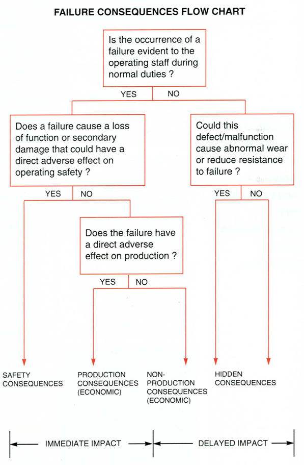
Evaluating failure consequences
The first step in developing an RCM programme is to evaluate the consequences of equipment failure. This identifies significant items and determines the priorities of the maintenance effort.
The different types of failure consequences include:
-
Safety consequences – possible fire, destruction or injury
-
Operational consequences – direct economic loss due to lost production plus cost of repair
-
Non-operational consequences – direct cost of repair only
-
Hidden consequences – reduced component life due to abnormal wear and contamination
Failure consequences can be evaluated by using the flow chart below
Evaluating maintenance tasks
The next phase of RCM analysis involves a systematic study of the different failure modes of each significant item to establish the benefits of scheduled maintenance. One needs to determine whether one of the basic maintenance tasks will satisfy both the criterion for applicability and the specific conditions for effectiveness. There is a specific order of preference to the use of preventive tasks as the Maintenance Task Flow Chart shows.
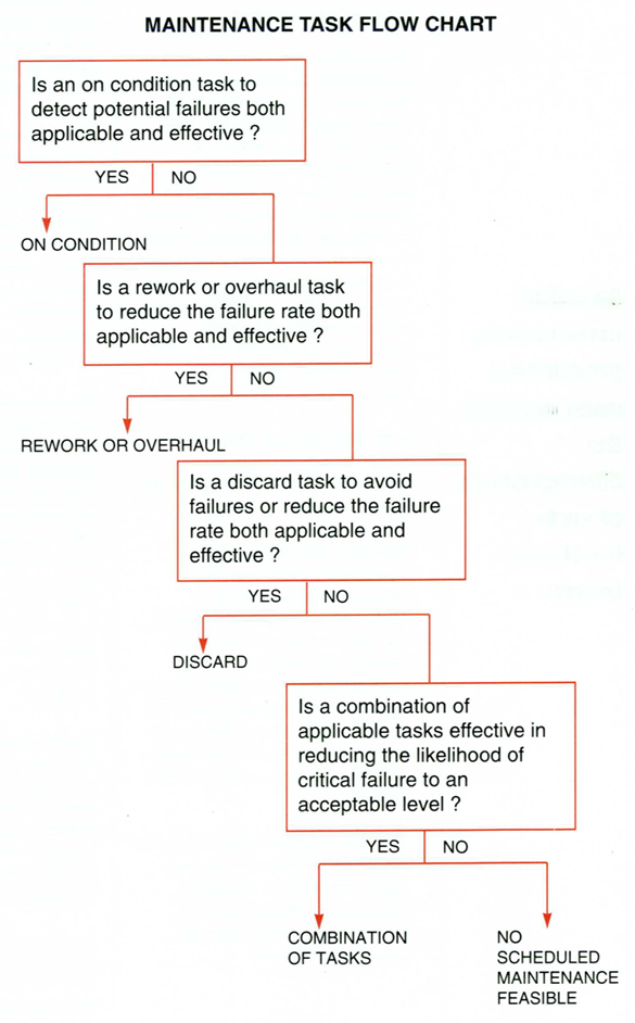
Scheduled on condition inspections directed at specific failure modes are the most desirable type of task. They are aimed at detecting reduced resistance to failure. The component remains in service until a potential failure is discovered. Where visual inspection is impractical, oil and filter analysis can detect abnormal wear and contamination.
On condition tasks include checking of pressures, temperatures, speeds, flow rates, output power, current draw, vibration, fluid levels, fluid leaks, cycle times, borescope inspections, and oil and filter analysis. These tasks discriminate between units that are likely to survive until the next inspection (sample), thereby allowing all units to maximise their useful life. Thus, when on condition tasks are applicable and effective the cost of both scheduled and corrective maintenance is minimised.
If no applicable and effective on condition task can be found, scheduled rework or overhauls are the second choice.
Scheduled discard tasks are economically least desirable. Although lubricant change is considered a discard task, it can be cost-effective because of its low relative cost. However, in large recirculating systems the oil itself is a significant and expensive item. Oil analysis can be used to monitor the serviceability of the oil and lengthen oil drain periods as well as check for wear.
If no tasks or combination of tasks are applicable and effective, the unit cannot benefit from scheduled maintenance. Replacement or product improvement/redesign should be considered.
Developing an initial programme
We are now ready to develop an initial maintenance programme for plant from the research that has been completed. We have already listed all the significant items that could benefit from maintenance, and a list of all known and envisaged functional failure modes for each component has been compiled.
We now consider the failure consequences of each functional failure. If a failure is found to have production consequences with plant downtime and loss of production predicted, the maintenance task flow chart is applied to that failure mode to determine applicable and effective maintenance tasks. The same logic is applied for safety, non-operational and hidden consequences.
The maintenance schedule should now be drawn up using conservative task intervals. Job cards are prepared detailing what tasks are to be done at a service. Task cards can be compiled to indicate how inspection and servicing are to be done and to define limits and procedures. Each task card is listed and signed for on the job card. Task cards are reusable and may contain illustrations and maintenance manual extracts. They should be sealed in plastic and used on the job.
Lastly, optimum service and inspection intervals are developed with operating experience. Tasks must be scheduled frequently to minimise failures, with the overall aim of finding a reasonable balance between low maintenance costs and low failure rates.
Examples
RCM decision-making logic is applied to two common industrial components as examples of how scheduled maintenance can extend equipment life.
Example 1: Industrial gearbox
Safety consequences? No
Operational consequences? Yes, loss of production
Economic consequences? Yes, cost of repair/replacement
Hidden consequences? Yes, contamination causing high wear rates
Functional failure mode: bearing, gear, shaft, or thrust washer failure.
Potential failure indications: abnormal wear and overheating seal failure.
Is on condition task applicable and effective? Yes
Is an overhaul task applicable and effective? No
Is a discard task effective? No
Is a combination of tasks effective? No
Initial scheduled maintenance programme for gearbox:
-
Visually inspect oil level (weekly)
-
Visually inspect for leaks and seal damage (weekly)
-
Test for overheating and high electric motor current (weekly)
-
Perform oil analysis to monitor oil and machine condition (every three months)
Economic considerations: n a small gearbox holding 0.5 litres of oil, the oil – and even the gearbox – is inexpensive to replace and oil analysis may not be cost-effective unless the failure consequences are critical or serious.
In a large gearbox holding 400 litres of synthetic oil at R45 per litre, the oil itself becomes a significant item and a capital asset. In this case oil analysis is warranted in testing for oil contamination and deterioration, and it has the added benefit of monitoring wear. The oil is changed only if it becomes unfit for further use.
Example 2: Industrial hydraulic systems
Hydraulic systems and their controls can be very complex so only the basic power pack is considered here:
Safety consequences? Yes, bursting hoses can cause injury and fire, and loss of power can result in loss of control over the load in cranes.
Production consequences? Yes, loss of production.
Economic consequences? Yes, cost of repair and fluid loss.
Hidden consequences? Yes, abnormal wear and contamination reduce component life
Initial scheduled maintenance programme:
-
Visually inspect fluid level (weekly)
-
Visually inspect for leaks and flexible hose damage (weekly)
-
Check system operating pressure (weekly)
-
Check load cycle times (weekly)
-
Drain off water and sediment accumulation (weekly)
-
Perform fluid analysis to monitor fluid and machine condition (every three months)
-
Perform filter analysis (every three months)
Economic considerations: In large systems holding a few thousand litres of hydraulic oil, an oil change can be extremely expensive. The oil should not be changed while it is still fit for service. Oil analysis can confirm oil integrity by testing the additive package, particle count and the level of other contaminants. Minor particulate contamination can be removed by external on-site filtration.
For more infomation please contact This email address is being protected from spambots. You need JavaScript enabled to view it. or +27(0)31 700 5460
Published in
Blog
Wednesday, 02 July 2014 11:40
Reliability-centred maintenance (RCM)

RCM embodies the best aspects of the four main maintenance philosophies.
Maintenance philosophies and practices have been around for many years – the objective of these philosophies being the economics consideration of optimising plant availability in industry. There has been a steady evolution from breakdown maintenance to preventive maintenance to predictive maintenance to proactive maintenance in the quest to keep industrial equipment operating economically, efficiently and safely.
Breakdown maintenance
Thirty years ago it may have been sufficient to adopt a breakdown maintenance philosophy whereby plant management would allow equipment to run to destruction and simply replace it at failure. In today’s economic climate this is no longer viable. Not only does the cost of repair or replacement have to be borne in mind, but the cost of down-time, lost production and safety must be considered. In the majority of cases, it does not make economic sense to manage a plant in this way.
Preventive maintenance
With the increase in the cost of machinery, spares and labour, and the cost of industry of lost or poor production, breakdown maintenance evolved into preventive maintenance in the late sixties and early seventies.
The objective of preventive maintenance was to organise a time-based schedule for service and overhaul of essential equipment. By using preventive maintenance it was hoped to eliminate or drastically reduce component failure and down-time improving productivity and profitability.
Predictive maintenance
Predictive maintenance was a great step in the right direction, but could only take maintenance philosophy so far, in that equipment was being checked, serviced and repaired on a regular basis and that history files were being kept on the equipment. One of the problems with preventive maintenance is that it is possible to over-maintain equipment; the cost of maintenance must be balanced against the cost of breakdown. This led to a shift from preventive to predictive maintenance.
The concept of predictive maintenance is to carry on with the planned preventive maintenance but, at the same time, conduct as many non-destructive tests on the items of plant to determine their mechanical integrity. Basically, this philosophy asks the question, “What is the point of fixing something that isn’t broken?” Oil analysis is probably the cheapest and easiest form of predictive maintenance to implement, but other techniques include vibration analysis, thermographic imaging, motor current analysis, balancing and alignment. It may be found that some failure modes cannot be detected by oil analysis on certain equipment, for example on non-lubricated components such as electric motors. In these cases other techniques must be employed.
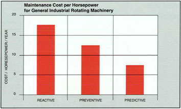
The bar chart below shows the maintenance costs for general industrial rotating machinery, comparing reactive (breakdown), preventive and predictive maintenance philosophies.
Studies have shown that a successful preventive maintenance programme can provide a 30% reduction in maintenance costs over a breakdown maintenance programme.
One important aspect of a predictive maintenance programme is that plant is not overhauled unnecessarily.
Contrary to popular belief, there is not a strong relationship between operating age and reliability. Once a piece of equipment has “bedded-in” and established a reliable operating mode, overhaul will disturb this mode and research has shown that the overhauled component will not last as long as the new component. If the predictive maintenance techniques employed do not indicate a problem, then don’t disturb a stable and reliable operating mode.
With the introduction of predictive maintenance and accurate record-keeping in machine history files, certain failure modes can be determined and this leads directly to a proactive maintenance philosophy.
Proactive maintenance
Proactive maintenance looks at root cause failure analysis (RCFA) to determine the cause of certain common failures in industrial equipment. If the cause of failure can be determined, can that cause be eliminated? Whereas previous maintenance philosophies have looked at predicting the failure of a component and taking action before the failure actually occurs, proactive maintenance looks at the root cause of failure and aims to eliminate the cause so that, in turn, that failure mode is also eliminated.
A good example of using RCFA in proactive maintenance is the influence of particulate contamination in the failure of fluid power systems. Research has shown that 70% - 85% of hydraulic component failures are due to particulate contamination, with up to 90% of these failures due to abrasive wear.
Predictive maintenance has established the cause of the majority of hydraulic system failures; the object of proactive maintenance philosophy is to eliminate that cause by keeping hydraulic fluids as clean as is practically possible. By regularly checking the cleanliness of hydraulic fluids, a large number of hydraulic component failures can be prevented.
Oil analysis forms an important part of proactive maintenance. In the example cited above, oil analysis is used to determine the cleanliness levels of lubricants so that dirty oils can be either cleaned or changed when unacceptable levels of contamination are detected. Although oil analysis is strictly part of predictive maintenance, it can also be instrumental in RCFA and can lead to good proactive maintenance practices. For example, oil analysis could be used to predict bearing failure in an automotive application. If the engine can be dismantled before actual failure then, firstly, subsequent damage can be avoided and, secondly, it is hoped that the cause of the bearing failure can be determined. This is particularly useful when one considers that certain failure modes, at the point of failure, can destroy the evidence of the cause of failure. In this way oil analysis can form an integral part of proactive maintenance.
Reliability-centred maintenance (RCM)
A lot of large industrial organisations have adopted the concept of RCM which encompasses all the best aspects of the four basic maintenance philosophies discussed above. Even breakdown maintenance has its benefits in certain applications (replacing a burnt out light bulb, for example)
The introduction of RCM to a company or organisation is not something that can be carried out overnight and the benefits are not likely to be immediately quantifiable. What is most important is that the company must have a maintenance philosophy or mission statement and a top-down management commitment to that mission statement. Only then can a RCM system be developed or expanded from existing maintenance systems. Management must be involved at all levels with regard to decision-making in the maintenance department before an effective maintenance philosophy can be implemented.
General acceptance of an RCM group by the workforce can sometimes be one of the biggest hurdles to overcome, because the maintenance planning department is frequently seen as a “police force” checking up on quality of work carried out by the artisans in the plant.
However, once an RCM programme has been instituted, developed and receives the full support of management and the workforce, then the company can look forward to dramatically increased reliability, productivity and safety as well as the ultimate benefit: increased profitability.
For more information contact WearCheck on +27(0) 31 700 5460 or This email address is being protected from spambots. You need JavaScript enabled to view it.
Published in
Blog
Tuesday, 17 June 2014 11:44
Stay on the ball with WearCheck

Olá! Calling all World Cup Soccer fans! We have created a special World Cup match schedule for you, which is available to download - free - from the WearCheck website.
The handy viewing schedule contains useful information such as the dates, times and which teams are playing in each match, and also includes places to keep a record of the scores in each match.
This will be particularly useful if you plan to keep a log of who is leading your office staff team draw at any given moment…eliminating the need for a referee to decide who wins the kitty!
So, to help you keep score and stay ahead of the game with WearCheck, download our World Cup Soccer schedule here!
Published in
Blog
Thursday, 12 June 2014 14:33
Silicon... Enemy number one. Part 2.

Using oil analysis to detect dust early.
Before the use of oil analysis, a dust entry problem would go undetected until a routine strip down or a failure occurred. Even then, often the wear would be attributed to lubricant breakdown or normal wear and tear. With the use of oil analysis, the picture changes. As soon as a dust entry problem occurs there is an increase in the silicon level of the oil and an acceleration of the wear pattern. As long as the oil samples are being taken at regular intervals in the correct manner, the dust entry will be detected at a very early stage. If effective corrective action is taken, the life of the component will be significantly increased, reducing maintenance costs.
It is beyond the scope of this article to discuss every type of dust damage in all components, so engines will be used as an example. Engines are at high risk to dust entry as large volumes of air are taken into the system and the close tolerances make it susceptible to even the smallest dust particle.
When an engine has a dust entry problem, the type of wear that takes place is related to the manner in which the dust enters. Therefore, by examining the type of wear taking place, it is possible to discover how the dust is entering the system. When studying an oil analysis report there are four possible wear patterns:
- Normal wear
- Increased top-end wear
- Increased bottom-end wear
- All wear rates increased
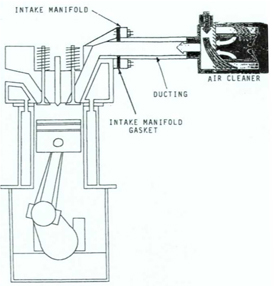
Image: Engine air cleaner system
1. Normal wear
It is unlikely that there will be a dust entry problem without an increase in wear rates. If normal wear patterns combine with high silicon readings, there are two main possibilities:
-
A silicone sealant, grease or additive is in use
-
Accidental contamination of the sample
Action to be taken
Check if an additive, grease or sealants have been used recently on the engine.
If no, check if correct sampling technique was used.
If yes, phone lab to confirm that additive can cause high silicon reading. If necessary, send sample to confirm.
If there is still doubt as to what caused the high silicon reading, a check sample should be taken.
Was the oil changed when the first sample was taken?
If no, send a check sample and, as a precaution, change the oil.
If yes, send a check sample only after the engine has run for 50 hours or 1000km.
2. Increased top-end wear
Increased top-end wear is caused by airborne dust that has been drawn into the combustion chamber being forced between the ring, piston and cylinder. This is caused by a defective air cleaner or a damaged induction system.
Action to be taken
Inspect the air filter element thoroughly, and check its seals and support frame for damage and distortion. Check the pleats for damage. If there is any doubt about a filter element, it should always be changed.
Next, check the induction hosing for damage, cracks, etc. and make certain that all hose clamps are secure. The breather and compressor are often connected to the induction system but are frequently overlooked. Check that both are functioning normally and their hoses are sound and secure.
Next, check the inlet manifold for cracks, and check that the gaskets are sound and secure.
Was a leak found?
If no, run the engine at idle and block off the air intake. The engine should stall within three seconds. If the engine does not stall, listen carefully at the joints for air being sucked in. Take a check sample after 50 hours or 1000km.
If yes, determine the condition of the engine. Check compression and blow-by. Repair the leak.
If normal, monitor the oil consumption as a safeguard.
If abnormal, schedule to have the piston rings replaced and the piston and liners examined.
3. Increased bottom-end wear
This indicates that dirt is getting into the lube oil directly and not past the piston and rings. The likely sources are:
-
Leaking seals
-
Defective breather
-
Damaged seal on oil filler cap or dipstick
-
Dirty storage containers and/or top-up containers
Action to be taken
Any dust which is in the oil will be pumped through the oil filter before entering the bearings. Therefore the first step is to examine the oil filter for:
-
Dust contamination
-
Bearing material
Was excessive dust found?
If no, check the sampling technique. Examine the oil filter at the next service.
Was bearing material found?
If no, monitor oil pressure and inspect the oil filter at the next service.
If yes, drop the sump and inspect all bearings. Replace as necessary
If yes, thoroughly check all seals and breathers, etc. Check the oil storage containers and top-up containers for the source of contamination.
4. All wear rates increased
This is the worst case. Carry out checks for top and bottom wear. Several other checks must also be done:
-
Was any repair work done to the engine? It is possible that the increased wear rates are due to a “rebedding in” process and silicon comes from contamination while the engine was open for repairs.
-
Piston torching. This is a rare occurrence but if a piston is torched by a misdirected or badly timed spray from an injector nozzle, silicon is released from the piston itself and all the wear rates will be increased. (Silicon is alloyed to aluminum to reduce its rate of expansion.)
For further infomation please contact WearCheck on +27(0) 31 700 5460 or This email address is being protected from spambots. You need JavaScript enabled to view it.
Published in
Blog
Monday, 09 June 2014 14:31
Silicon... Enemy number one.

External contamination of lube oil by silicon (dust) is a major cause of accelerated wear.
After oxygen, silicon is the most abundant element in the earth’s crust. Silicon does not occur naturally in elemental form but rather combined with oxygen in a compound called silica (silicon dioxide.) Silicon occurs in a free form (quartz, sand, etc.) or combined with a variety of metallic oxides, in which case it is called silicate (eg. Felspar).
Another class of silicon compounds that should not be confused with silica and silicates is silicones. Silicones are man-made organic compounds that find extensive application in the polish, paint and lubrication industries.
Silica and silicates make up a large proportion of the earth’s crust and as such are present at high concentrations in natural solids and dusts. It is for this reason that silicon is used as the main indicator of dust entry into a component. There have been several studies done on the causes of premature wear in components. The figures vary from study to study but one thing is clear: external contamination of lube oil by silicon (dust) is a major cause of accelerated wear.
The South African climate generally is one of low rainfall with resultant high dust levels. Particles of airborne sand and dust vary in size, shape and abrasive properties. In an engine the ingress of atmospheric dust takes place primarily through the air intake. Efficient air filters remove 99% of the dust that an engine ingests.
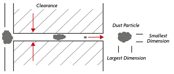
Image: Dust particles
The remaining 1% consists of very small dust particles that pass through the air filter. These vary between submicron size particles to particles up to 10 microns in size. The dust will pass between piston, rings and cylinder and eventually become suspended in the lubricating oil.
It is the particle that has its smallest dimension of a similar size to the clearance involved that does the maximum damage. A particle smaller than the clearance will pass straight through doing little harm. A particle larger than clearance will be unable to enter and do any damage. (See diagram above)
In an engine the clearance between the piston ring and liner bore is extremely small, therefore it is the small light airborne dust particles which are the biggest threat when a leak occurs in the induction system.
Under ideal conditions the working surfaces of a component are kept apart by a thin film of oil. This oil film prevents direct contact between the surfaces, reducing the amount of friction and the rate of wear. The oil film will also absorb shock loads and help distribute the load over the whole surface. The introduction of even a small amount of dust into this environment will seriously disrupt this. Once the dust particle has entered the oil film it forms a direct link between the two surfaces, nullifying the effects of the oil film.
The first and immediate effect is a “scratching” of the surface as the particle is dragged and rolled across the surfaces. The second and potentially more serious problem is that once the dust particles is introduced in between the two surfaces, it changes the loading of the surface from an even distribution to a point load concentration on the particle with tremendous increase in pressure at this point.
The increase in pressure causes a deflection of the surface, which will eventually result in metal fatigue and the surface breaking up.
The solution is to keep the dust out. To do this, design engineers use air cleaners, breathers and seals at any point that dust may enter.
Air cleaners filter air as it is drawn through a system, e.g. in engines, compressors, etc. They have to deal with large volumes of air, as an engine needs up to 2000 litres of air to burn 1 litre of fuel efficiently. The most common type of air cleaners have three main components: a centrifugal precleaner, a large pleated paper element, and a smaller paper or cloth “safety element”.
The precleaner consists of radial fins and a collection bowl. The fins cause incoming air to swirl rapidly around the inside of the housing. The heavier dust particles are thrown outward by centrifugal force and are channelled into the dust collection bowl. Some bowls have an automatic discharge valve; other bowls have to be removed from time to time to clean out the accumulated debris before its overflows into the filter housing.
The main filter element traps the remaining dust particles as the air is drawn through the paper pleats.
The smaller safety element is fitted after the main element in case the main element is damaged in any way. Its purpose is to trap any dust introduction when the main filter is changed. It does not filter as effectively, however, nor can it hold the same volume of dust.
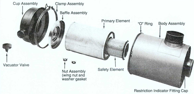
Image: Air cleaner
Breathers are used to allow air to flow in and out of a component. As a components temperature increases in operation, the internal air expands with the increase in temperature with a resultant increase in pressure. If this air was not allowed to vent to the atmosphere, the build-up in pressure would force the air out at the weakest point, normally the seals. As the component cools down after operations, air is once again drawn in through the breather. If it is unable to draw in air, for example if the breather is blocked, then air will be pulled in past the seals with the danger that it may draw dust into the seal at the same time.
Seals prevent oil from entering or leaking out of a component wherever there is a danger of this happening. There are many different types of seals in use today, but as a rule of thumb “if oil can get out, dust can get in”. A leaking seal should always be replaced.
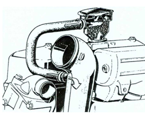
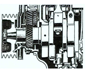
Images: Engine breather of turbocharged engine & front crackshaft oil seal.
End of part one...
Published in
Blog
Sunday, 25 May 2014 06:58
SAIT National Awards

Following the recent South African Institute of tribology (SAIT) annual national awards dinner in Johannesburg, WearCheck is very proud to report that our senior diagnostician - Steven Lara-Lee Lumley - was awarded the prize for best technical presentation, for her paper entitled "The winds of change - The role of oil analysis in wind turbine gearbox reliability". The award-winning paper was presented at the SAIT technical meeting in March 2014.
‘Being singled out to win this top industry award is a great honour for Steven, ‘ says WearCheck MD Neil Robinson. ‘Gaining recognition for her work above experts from all around South Africa has given credit to both Steven and WearCheck for producing top quality work. Well done, Steven!’
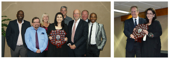
Above left: (from left to right) Isaac Mabaso, John Evans, Lorain De Bruin, Award-winner Steven Lumley with the trophy, Gert Nel, Derek Hanekom (Minister of science and technology, SAIT), Ashley Mayer, Ernest Moremedi.
Above right : Steven Lumley receiving her award from David Beard, SAIT Executive Committee President.
Published in
Blog
Friday, 09 May 2014 11:39
African Utility Week

WearCheck invites you to attend and interact with our sales and technical teams at this year’s African Utility Week (AUW) exhibition at the Cape Town International Conference Centre on 13 and 14 May 2014.
Our full range of condition monitoring products will be showcased at the AUW. In particular, our transformer and wind turbine oil analysis programmes, as well as the services of our thriving reliability solutions division - including vibration monitoring, thermal imaging, laser alignment and balancing.
Come and meet us at stand HY08, at Cape Town ICC, 13 – 14 May 2014.
Click here to register for a complimentary access pass from WearCheck.
Published in
Blog
Monday, 05 May 2014 08:38
WearCheck harnesses the winds of change

WearCheck recently developed and launched a condition monitoring kit which is designed specifically for wind turbines, aiming to boost their reliability and reduce operating costs.
Wind power is the world's largest growing energy source thanks to advancing wind turbine technology. Wind turbines have the potential to generate enough power to meet the growing need for electricity, and simultaneously reduce consumption of water and emission of pollutants such as carbon dioxide.
So says WearCheck senior diagnostician Steven Lara-Lee Lumley.
‘However,’ she notes, ‘barriers to widespread acceptance of wind turbines include their reliability, costs of operation and maintenance of the equipment relative to alternative means of power generation.’
‘Oil analysis, along with other condition monitoring tools, offers the potential to effectively manage gearbox maintenance by detecting early damage as well as tracking the severity of the damage. This, in turn, boosts the reliability and availability of the various wind systems. It is for this reason that most OEMs recommend routine oil analysis as part of an effective maintenance strategy.
In Technical Bulletin 58, which can be viewed here, Lumley discusses the various preventive maintenance options that are available to the wind power industry.
Published in
Blog
Thursday, 20 March 2014 13:17
MMEC Mozambique exhibition

WearCheck Mozambique – WearCheck’s 10th laboratory, and the newest one to open, in March 2014 - will be present at the 4th MMEC exhibition & conference, which takes place in Maputo, Mozambique at the Joaquim Chissano Conference Center from the 26th to 28th March.
The event focuses on the Mozambique Mining, Energy, Oil & Gas sectors and their sustainable development.
Quinton Verster of WearCheck will be available at stand 8 to assist you with all your Oil Analysis and Condition Monitoring needs.
For more information, contact Quinton on This email address is being protected from spambots. You need JavaScript enabled to view it., visit www.wearcheck.co.za, or contact head office in South Africa on telephone +27 (0) 31 700 5460
Published in
Blog